Tuesday, December 4, 2018

Two-Factor authentication with Azure sphere and Azure IoT hub

Introduction

This blog post introduces to a new way of carrying out two factor authentication using Azure Sphere. As more and more devices are being added to IoT world, there has been increasing need for a device that is secure and connects to Azure IoT to further automate the process. Azure Sphere fills that gap of secure communication. More information on Azure Sphere can be found at: https://azure.microsoft.com/en-us/blog/introducing-microsoft-azure-sphere-secure-and-power-the-intelligent-edge/

The intended goal of this blog post is to present a use of Azure Sphere. The best way to understand any technology is by creating a product or use that shows how the technology works and how it can be leveraged. This blog post presents a use of Azure Sphere by introducing a way to implement "Two factor authentication".

Information on how to setup Azure Sphere can be found in my previous blog post at: Getting started with Azure Sphere


Disclaimers

The information provided in this blog is intended to demonstrate a novel use of Azure Sphere. It does not recommend the "Azure Sphere based two factor Authentication" be used in production environment. The recommendation is to use the material provided in this blog as an opportunity to learn and understand Azure Sphere and Azure IoT.

Typical two factor authentication

Let us start by looking a typical two factor authentication. In traditional two factor authentication, a user (using a supported device like, smart phone, desktop or tablet), initiates the authentication by providing a user name and password to the authentication provider. Typically an authentication provider is the system that is part of a web site or an application. The authentication provider takes the user name and password and authenticates the user. This user of user name and password constitutes the first factor of the authentication. On successful authentication of the first factor (user name and password), the authentication provider sends a code to device that is associated with the user who is requesting the authentication. Typically the code sent through text or a phone call. The user receives the code. The authentication provider then provides a page for the user to enter the code that is sent. This code constitutes what we call the second factor. On receiving the second factor (code) the authentication provider verifies the code and completes the authentication process. 
Following diagram illustrates the typical two factor authentication flow.

Figure 1 - Typical two factor authentication flow

Two-Factor Authentication using Azure Sphere

The Two-Factor Authentication using Azure Sphere uses the same authentication mechanism for the first factor (i.e. username and password). But for the second factor it leverages the Azure Sphere device. The Azure Sphere device is attached to a device that is being used by the user requesting the authentication. This replaces the need to have the authentication provider send a code to a user device (such as phone for text message). Instead it relies on the Azure Sphere attached a users device to carryout the second factor authentication. The Azure Sphere device is connected to Azure IoT and that communication is secured by design.
The inspiration of using Azure Sphere as the second factor authentication device came from a paper called "The Seven Properties of Highly Secure Devices" published by Galen Hunt, George Letey, and Edmund B. Nightingale of Microsoft Research. Here is the link for that paper: https://www.microsoft.com/en-us/research/wp-content/uploads/2017/03/SevenPropertiesofHighlySecureDevices.pdf

Why use Azure Sphere for second factor authentication


  1. Hardware based security. As mentioned in the "The Seven Properties of Highly Secure Devices" paper, the "Highly secure devices have a hardware-based root of trust." Here is the excerpt from that paper.
    Highly secure devices have a hardware-based root of trust. Device secrets are protected by hardware and the hardware contains physical countermeasures against side-channel attacks. Unlike software, hardware has two important properties that may be used to establish device security. First, single purpose hardware is immune to reuse by an attacker for unintended actions. Second, hardware can detect and mitigate against physical attacks; for example, pulse testing the reset pin to prevent glitching attacks is easily implemented in hardware. When used to protect secrets and device correctness, hardware provides a solid root of trust upon which rich software functionality can be implemented securely and safely. 
  2. Secured Communication: The communication between the Azure Sphere device and Azure IoT hub is secured by Azure. As system implementor we would not need to secure the communication as we are leverage Azure for that. 

Prerequisites

  1. Since Two-Factor Authentication using Azure Sphere is based on Azure Sphere device connected to user's machine, it is important to mention that the prerequisite of this system is to have Azure Sphere device properly connected the user's machine. Information on setting up Azure Sphere device with a machine is provide in previous blog post Getting started with Azure Sphere
  2. The second prerequisite is to make sure the Azure Sphere device has been added to an Azure IoT hub. More information for that can be found at Microsoft Docs article Set up an IoT Hub for Azure Sphere

Authentication Flow with Azure Sphere

As mentioned above the first step is validating the factor 1 which is typical user name and password authentication. The following steps illustrates the flow information and authentication mechanism for the factor 2 (security code):
  1. User provides the user name and password that is passed on to the authenticator (authentication provider). 
  2. The authenticator validates the user name and password thus completing the factor 1 authentication. 
  3. After that authenticator sends message to Azure Sphere device attached to the user's machine to generate a security code and instructs the user to press the Button 2 on the Azure Sphere device. Information on setting up Azure Sphere device is provide in prerequisite section mentioned above. 
  4. The Azure Sphere device receives the request through its connection to Azure IoT hub. 
  5. It then generates a security code, saves the security code in its mutable memory and posts the result to Azure IoT hub. 
  6. Azure IoT hub informs the authenticator (authentication provider) about the generated security code. 
  7. As instructed by the authenticator, the user presses the Button 2 on the Azure Sphere device. 
  8. The Azure Sphere device retrieves the saved security code and posts the information to Azure IoT hub. 
  9. The authenticator then receives the notification that user has pressed the Button 2 along with the security code that was retrieved by the Azure Sphere device from its mutable memory. 
  10. The authenticator then validates the security code retrieved previously when Azure Sphere generated the security code and when the Button 2 was pressed. 
  11. Based on the authentication result, the user is deemed authenticated or not.
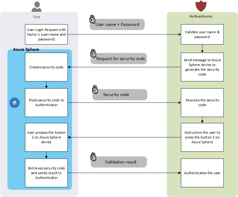
Figure 2 - Two Factor Authentication using Azure Sphere


Conclusion

Although Azure Sphere is quite powerful and versatile, we have seen how we can leverage Azure Sphere and Azure IoT hub to provide the second factor authentication for a two-factor authentication system. There are other systems that can be build on top of the design that is presented here. If we look further, we can connect another device with Azure Sphere device that provide other uses. For example, we can provide a display to show the security code that is generated by the Azure Sphere device that can be entered into an interface provider by the authenticator.

In my next blog post, I have taken provided technical details on how Two-Factor authentication is implemented using Azure Sphere and Azure IoT hub. The details are provider at: Two-Factor authentication with Azure sphere and Azure IoT hub - Step by step

Comments are welcome.


Sunday, November 25, 2018

Leveraging Built-in endpoints in Azure IoT Hub

Introduction


One of the great features of IoT hub is its built-in systems endpoints. This allows us to quickly hook into event hub belonging to an IoT hub without the need to an EventHub, Azure Storage containers, Service Bus queues and Service Bus topics.

In this post, we are going to look into how to easily we can leverage the built-in endpoints in Azure IoT hub by creating a simple application using Azure Functions.

When you have an Azure IoT hub and want to hook into events generated by Azure IoT hub, you have two main choices.

1. Events provided as part of Azure Event Grid
Using Azure Event Grid we can use resources such as Logic Apps, Azure Functions, Web Hook, Storage Queues, Event Hubs, and Hybrid Connections.

2. Built-in endpoints

This is the built in endpoint that every Azure IoT hub offers as part of its infrastructure. Using Built-in endpoints we can hook into system and device messages. So when a device sends a message to Azure IoT hub, this "Built-in endpoints" to receive those messages.

Figure 1 - Built-in endpoints view

Using Built-in endpoints

To use built-in endpoints, we will create a custom Azure functions that uses the built-in endpoint to listen to messages emitted by the device to Azure IoT hub. We will  use the following steps to accomplish that.

Step 1- Get Event Hub-compatible endpoint

  1. Open the Azure portal and navigate to Azure IoT hub. 
  2. Click "Built-in endpoints" in the navigation pane. This will show a view that is similar to view show in Figure 1.
  3. Copy "Event Hub-compatible endpoint" and save it to be used in the Azure Function app that is mentioned in Step 2.

Step 2 - Creating Azure Function App

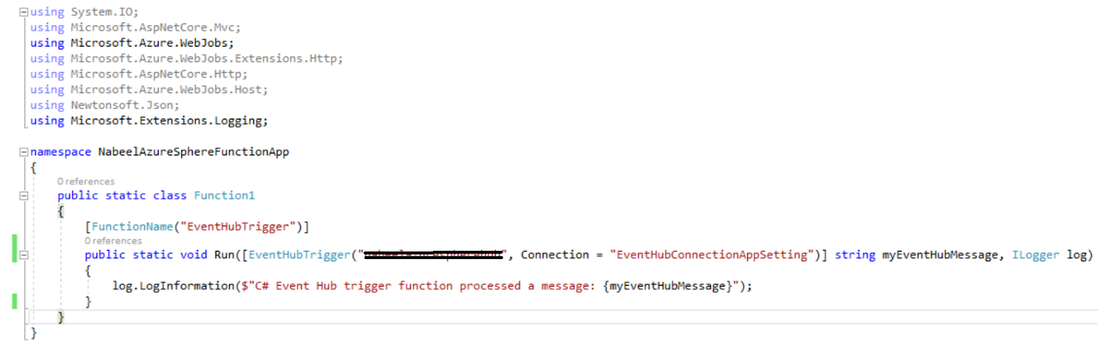
1. Using the boiler plate project that is created when Azure Function App is selected, we can modify the code  as shown below.
Figure 2 - Azure function code

2. Update connection string:
Using the connection string saved in Step 1, update the local.settings.json as shown below:
Figure 3 - Event hub connection string using Built-in endpoint


3. Managing dependencies:
In order to use the Event Hub triggers, we have to add the following NuGet packages:
Figure 4 - Dependencies


Conclusion

We have seen how easy it is to use Built-in endpoints to hook into  Azure IoT hub events. Although we have used Azure Functions app to demonstrate the application that is listening to Azure IoT events using Built-In endpoints, we can use any application platform that can be invoked using EventHubTrigger.

Thursday, November 1, 2018

Getting started with Azure Sphere

Azure Sphere - MT 3620 on my work desk


Note: This is first of a series of blog posts that are related to my work done on Azure Sphere. Stay tuned for more on Azure Sphere.

Introduction

One of the best to learn a new technology is to just get hands dirty start work on the new technology. In this blog,  I will take you through the steps that I carried out in order to start work on Azure Sphere.

Once you have received the Azure Sphere device, it's time to get started. Here is the link https://azure.microsoft.com/en-us/services/azure-sphere/get-started/that will take you through the steps of acquiring a Azure Sphere device.

1. The very step is to attached the device with your development machine. If you have the correct operating system then the device manager should automatically install the drivers. In my case the drivers for the device did not install automatically so I had to go to a special page that allowed me to download the drivers. Visit http://www.ftdichip.com/Drivers/VCP.htm to download the driver. The following image shows the driver that I downloaded for my development machine:


2. Once you downloaded and install the drivers, your device manager should look like as the following image.


Notice the three USB Serial Ports (in my case I got COM 4, COM 6 and COM 7)


3. Download Install Azure Sphere SDK for Visual Studio Preview.

4. The Azure Sphere SDK for Visual Studio Preview would install the Azure Sphere Developer Command Prompt Preview. This command line utility is your bridge between the Azure Sphere device and your development effort.

5. Run azsphere login command on  "Azure Sphere Developer Command Prompt Preview" to ensure you can Azure Sphere SDK has been properly installed and you can access your subscription.

6. Creating a Tenant
azsphere tenant create --name mytenant

0000000-xxxx-xxxx-xxxxx-xxxxxxxxxx mytenant


7. Claiming the device
azsphere device claim

Claiming device.
Successfully claimed device ID 'XXXXXXXXXXXXXXXXXXXXXXXXXXXXXXXXXXXXXXXXXXXXXXXXXXXXXXXXXXXXXXXXXXXXXXXX' into tenant 'afrinish' with ID '0000000-xxxx-xxxx-xxxxx-xxxxxxxxxx'.
Command completed successfully in 00:00:03.3873192.


8. Configure Wi-Fi

azsphere device wifi add --ssid [[yourSSID]] --key [[yourNetworkKey]]

Running the command would yield the following output.

Add network succeeded:
ID                  : 0
SSID                : XXXXXXXXXX
Configuration state : enabled
Connection state    : unknown
Security state      : psk

Command completed successfully in 00:00:02.0253617.


Conclusion

In this blogpost, we have gone through the steps of getting started with Azure Sphere. We started off by acquiring the device, installing necessary software and drivers, configuring the device and connecting it the Wi-Fi. If there any any issues, please use the comments section to ask questions.

The next step would be to start developing. Happy coding!

Tuesday, September 4, 2018

Multi-cloud Architectures for Applications

Multi-cloud architecture for distributed application

Back story

Companies are embracing cloud as part of their key business strategy. Huge part of this embrace is moving their applications to cloud. This created a challenge for major cloud providers, like Amazon, Microsoft and Google, to offer a slew of services that would help companies move to cloud. That brought us to era of cloud architectures. Huge progresswas made (and still is being made) in this area.

As progress was being made in moving to cloud, a risk emerged called “vendor lock-in”. This essentially meant that when the applications where being moved (or even when new applications where being created), the architecture was focused on the services that were provided by on cloud one cloud vender. This is critical because this makes the consumers of applications more vulnerable to dependencies. This was not the only risk that emerged but this was the most significant
and attention.

To remedy that “Multi-cloud” or “Portable” architecture was embraced. Applications were architected in such a way that they could be ported from one cloud provider to another without any major rewrites. New technologies like Kubernetes, Docker and services orchestration technologies went along way to provide underlying technologies to mitigate the “vendorlock-in” risk.

What is Distributed Application Multi-Cloud architecture?

The multi-cloud architectures were great in providing resiliency and removing underlying dependencies which would have locked in to a particular vendor. This made solutions architects to focus on treating their solution as one big entity deployed in redundant fashion. It took focus away from actual application architecture and its nitty gritty details that would have been leveraged by cloud.

“The basic idea of Distributed applications multi-cloud architecture is to architect a solution that is leveraged to the max by cloud and not bounded by the offerings of a cloud provider”.

Every application, albeit micro service or not, is made of constituent components, services or layers. In Distributed Application Multi-Cloud architecture, the architects focus on application’s different components and treat them as components, services or layers that can be deployed to any cloud to gain the maximum benefits.

Advantages of Distributed Application Multi-Cloud architecture

As stated earlier, Distributed Application Multi-Cloud architecture is the evolutionary form of Multi-Cloud architecture, it carries all the advantages of Multi-Cloud architecture. In addition to those advantages, Distributed Application Multi-Cloud architecture offers following advantages:

1. Extra layer of robustness: Since the focus is on the on application’s different constituent components/layers/services, the architecture achieves an extra layer of robustness.

2. Best use of resources: Cloud providers (mostly big cloud providers like Amazon, Google and Microsoft), offer different services with their own pricing model. When a service offering comparison is made between these cloud providers, it would be apparent that some services would be cheaper than other cloud service providers and some would be more expensive than other cloud providers. A Distributed Application Multi-Cloud architecture can provide a solution that would take advantage of the difference in pricing model for different services offered by cloud providers to the advantage of the company for which the solution is being architected. This can translate into considerable cost
advantage.

Here is an example:
You have an API that needs to be deployed with access to general public. This API requires a backend storage. It might make sense to use Azure App Service to host the API and use Azure’s blob storage for the backend storage. But hypothetically, it might appear that using Google’s cloud storage product be a cheaper option without sacrificing application performance.

3. Higher level of services statelessness: As the application’s constituent services are distributed to different cloud providers, a higher level is achieved for the constituent services.

Tenants of Distributed Multi-Cloud Applications Architectures

• Distributed multi-cloud application architectures is the concept for architecting solution to achieving maximum advantage by harnessing service offerings from any cloud provider.

• Focus on looking at the Application’s constituent components as separate entities that can be leveraged to achieve maximum benefit.

• Not every cloud architecture would be a good fit for Distributed Applications Multi-Cloud architectures.

Step by step guide

1. Review application architecture. The end result of this step is an in-depth understanding of the application, its behavior and environment.

2. Identify constituent components of the architecture. This step should yield a list of all the constituent components of the architecture that make up the whole architecture. This very important step as if the constituent components are not identified properly then benefits of the multi-cloud would not apparent.

3. For each constituent component, identify components that can be deployed/hosted on cloud. This would yield constituent components that can be moved/hosted on cloud.

4. For each cloud component (constituent components that can be moved/hosted on cloud), identify the cloud component that can be deployed/hosted on multi-clouds.

5. Re-architect the application based on previous step. This step should yield an architecture that is multi-cloud.

6. Go through each component of the multi-cloud architecture and use a decision tree (give below) to identify if that component should leverage multi-cloud or not. At the end of this step, you will have each component identified for multi-cloud or not.

7. Analyze the architecture as a whole for determine if the multi-cloud should be used. The rationale of this step is to see if there is cost/performance/security benefit that would be leveraged using multi-cloud. If there is only one component that can be leveraged using multi-cloud (and produces considerable benefits as one), then it might not make sense to use multi-cloud.

Wednesday, September 14, 2016

Continuous delivery with Azure App Service

Update:

Click here for the SoCalCode camp presentation about this topic.

Introduction


This post would introduce you to continuous delivery pipeline using Azure app services. We would take a use case and implement the steps that we need to take in order to establish a build pipeline.

What is Continuous Delivery?

In simple words “Constantly develop, automatically build and automatically deploy”. This means that as soon as code is checked in a system would automatically build the application and deploy.

Azure App Services

Azure app services is a set of technologies that enable development of cloud centric Web Apps, Mobile Apps, API Apps and Logic Apps. There is a great introduction to App Services presented at: https://azure.microsoft.com/en-us/documentation/articles/app-service-value-prop-what-is/ .


Power of App Services

To understand the power of Azure App Service you have to compare to a classic Web Application with any of the technology such as Azure App Service Web App. In a classic Web App, a web server such as IIS is the main component. The Web App is installed on IIS and the pages are served through IIS to internet audience. This is a typical on premises infrastructure implementation. You are responsible for managing the security, availability, scale and instrumentation. Part of the classic web app infrastructure is the responsibility of not only delivering the web app but maintenance of the web server. This includes the separation of environments such as development site, QA site, UAT site and the production site. Also, since web server maintenance is part of this infrastructure, you have to also think about the actual server where that web server is installed. The environment that server offers greatly effects how the web server would work. This is another layer of responsibility that a web developer has to keep in mind.
With the App Services, the IIS part has been abstracted away. This means that management of web server (for example IIS) is not the focus but the focus is the delivery of web app. As an application developer we can easily create on App and have it hosted in different deployment slots. These deployment slots makes it easy to create environments such as development site, QA site, UAT site and production site for the same web app.


Continuous delivery pipeline for Azure App Service

Since web server and the server hosting the web server is not part of Azure App Service, the establishment of continuous delivery pipeline is very easy to establish.
Our focus for this post is to list the steps and design patterns that we can use to establish the continuous delivery pipeline.
There are three major steps to establishment of continuous delivery pipeline for Azure App service. These are:


Establishment of development slots

Once you have created an Azure Web App, you have to define its deployment slots. Usually the deployment slots are representation of your different environments. For example, in a typical web development effort you would have following environments:

1.      Development: This is the environment that is used by development team to help them develop different aspects of the project. Typically this is referred simply as “dev”.

2.      QA: This environment is used by the QA team to test the web app separate from the development environment. This is great for providing isolation and also to do better validation testing. Typically this is simply referred as “qa”.

3.      UAT: This environment is used by product owners or stake holders to validate different features after the QA has signed off. Again an isolation from dev and QA allows the UAT to test the web app irrespective of the test data that QA has used to valid. Typically this is simply referred as “uat”. Usually a separate database is attached for the UAT environment.

4.      Staging: This sometimes also known as pre-production. Typically is used to validate the build process and once the build is validated, this environment is swapped with production. Usually the staging environment uses the same production database. This allows the swapping from staging to production seamless without any down time. Typically this is simply referred as “staging”.

5.      Production: This is the actual web application that represents the production environment. Typically this is simply referred as “prod”.

The Azure App Service gives each deployment slot a unique URL. This essentially means that each of the deployment slot is a separate web application. Each of the web app URL representation of the environment is used by different team members. Development team members use the dev URL, QA uses the QA URL, and UAT uses the UAT URL for the web app.
Here is an example of different deployment slots for our API web app.


Establishment of branching strategy

There are a lot of different branching strategies that are used in the industry. The branching strategy is designed or sometimes evolved based on respective objectives. One of those objectives is the environment. What it means is that for different environments different braches are established. To simplify let us take the following branching strategy.

Master branch – For Development environment
QA Branch – For QA and UAT environments
Production – For staging environment


Importance of branching strategy means for continuous delivery

Since the main tenant of continuous delivery system is to automatically we build and automatically from a code check in, we have to pay extra attention to where the code check in takes place. If we look at our branching strategy, it would mean that if we check in the code in the master branch then dev environment should be build. If we check in the QA branch then it means that QA and UAT environments would be build. Same goes for the staging environment. This is why your branching strategy should be representative of your build environments. Let us take a typical scenario to explain more:
Joe (Backend developer) completes first part of the story and checks in the code to master branch. This kicks off a fresh “dev” build.
Jessica (Front end developer) completes the second part of the story and checks in the code. This kicks off another fresh “dev” build. Since the second part of the story completes the story. The build manager merges the master branch into QA branch. This kicks off a QA build and a UAT build for both QA and UAT team members.


Establishment of build/publish process

Azure App Service deployment

There are multiple ways to deployment apps on Azure App Service.  There are:

FTP

This is a most direct and classical way of deploying any web app. The major drawback is that this a total manual process. If you need to automate this, you have to write quite complex scripts.

Web Deploy

This tool allows you to directly deploy web apps to azure app service from visual studio. Although you do not have to use FTP for this scenario but you still have to do actual deployment manually.

Kudu

This build engine is used where we want to have automatic build/publish execution when a source code repository is attached. This means that as soon as a check in take place on a branch (established in step 2), the kudu build process would kick in a do the rest.


Code checked-in to repository  >>  Kudu initiates the build >> Kudu publishes the website


Multiple web apps challenge

The above mentioned steps would work great if you have only one web app in your code repository. For example, you have create a dedicated branch for one web app that has one solution file (.sln). The challenge comes in the shape of a scenario where you have multiple web apps and they all share the same code repository. For example, in a typical business application, you might have one web app that serves the pages and one Web Api app that is consumed by the web app. You might have different release pipeline for WebApi and web App. In this scenario the visual studio solution would contain both projects as part of the solution.
To accommodate the scenario of multiple web apps projects in a solution, you have to take some extra steps.

Step 1. Add app setting to your App Service to uniquely identify your app. This is to give Kudu a way to kick start the build and complete the publishing once code has checked in.


Step 2. Add “.deployment” file to the base of your source code repository. The “.deployment” file gives Kudu a starting point to start the deployment process. Here is a sample:


As you can see what the “.deployment” file is asking Kudu to do is just to call deploy.cmd file. We would look at this in next step.

NOTE: 
Before proceeding further it is important to note that following are prerequisites for the next steps:
1. Nodejs: https://nodejs.org/en/
2. azure-cli: https://azure.microsoft.com/en-us/documentation/articles/virtual-machines-command-line-tools/

Step 3. Create deploy.cmd file. This is the file that would tell Kudu how many different web apps or web Api apps are available in your code base that needs to be built as part of continuous integration pipeline. 

Here is an example of deploy.cmd file:


If you look at this file, you would notice that there are three web apps that are mentioned in the code. These are the three projects that are part of same solution file. What this code is doing is checking which App Service has kicked started the build process. This essentially means the branch where the code check in has happened. The SITE_FLAVOR comes very handy here as we use this App setting to identify the application.


After the app service identification, the deploy.cmd is just calling the corresponding individual deployment files. In our examples there we have three different deployment files. Those are:
deploy.customersapi.cmd
deploy.customersweb.cmd
deploy.anotherapi.cmd
In our next step we would see how you create these individual deployment files.


Generating Deploy.customer.cmd

 Step 1:

Assuming that your customerapi’s project file is at c:\sites\CustomerApi\src\CustomerApi.csproj and customerapi’s solution file is at c:\sites\CustomerApi\src\CustomerApi.csproj and c:\sites\CustomerApi\CustomerApplication.sln. Execute the following command using elevated Administrator mode either on command prompt or Powershell prompt. I always prefer PowerShell because of ease use.

azure site deploymentscript --aspWAP c:\sites\CustomerApi\src\CustomerApi.csproj  -s c:\sites\CustomerApi\CustomerApplication.sln


      Step 2:

Running the above command would yield a file called deploy.cmd. Rename file deploy.cmd to deploy.customersapi.cmd.

Step 3:

Repeat steps 1 and 2 for customersweb and anotherapi projects.


Conclusion

Azure App services are set of very powerful technologies that gives a very clear pathway to establish a continuous delivery pipeline.

SocalCode Camp presentation

The following presentation about this topic presented at the 2016 SocalCode camp.


Wednesday, June 10, 2015

Mobile User Membership Architecture with Mobile Services Backend

Introduction

We have reached to a point where mobile apps have become essential. The two big groups of mobile apps are natives and mobile web apps. There is a separate discussion about which type would make more sense, when that would be the case and why in general. The thing to takeaway is that mobile web app is actually a type of web site. So when talk about user membership architecture, we are essentially talking about user membership for a website. But when we are talking about native apps, the user membership architecture is different from mobile web because of the capabilities a native app contains in itself. In this blog, I am going to focus on the user membership architecture for native app site of mobile world.

Mobile User Membership Architecture

A user membership architecture is a design that shows how a user of an app is formally defined as "User" of that mobile app. The reason I put emphasis on word 'user' is because there is a very essential process that has to take place which will qualify user of an to app to a "User". When the qualification has taken place then the "User" is now identifiable as an entity to the Mobile Service Backend. To understand that let us take a scenario where you have developed an App and distributed the App to the market. To user that App, anyone can download the app and use it. The App does not know anything about the user. On top of that the Mobile Services Backend does not know anything about the user of the App either. So when the Mobile Services Backend does not know about the user then there is no analytics related to users of the app. Also, if you wanted to have a provisioning feature in the app, you cannot do that because there is no distinction between the users. So User Management Architecture is the path that you an use to define and qualify a user of an App. 

The main components of Mobile User Membership Architecture are:
  • User creation or signing up process
  • User authentication process
  • Mechanism for user logging in
  • User logging out mechanism
  • Mechanism to retrieve/reset user password or any other property of user entity
  • Optional: Mechanism to let anonymous user to log in
  • Optional: If anonymous user is allowed then there should be mechanism to convert them to regular users if requirement exists

Fig. Mobile User Membership Architecture


Conclusion

User membership is way too important to be ignored for any mobile device app. This is a vast field. In this post I have tried to explain in simple terms what choices we have. But there are more details and intricacies that are in the play for user management on mobile devices. This post gave you a high level introduction. In my subsequent post, I will try to go in more detail for each of the components and explain with code examples. Stay tuned.

One of the great ways to acquire knowledge is to share knowledge. Please do share your experience and knowledge by commenting so we all can better design great mobile applications.

Monday, June 8, 2015

Why cloud-based mobile backends makes sense

Update:

Due to the announcement by Parse to shutdown it is services, the examples mentioned in this article related to Parse are no longer valid. However, the same principals are valid on other cloud platform such as as Microsoft Azure.

Background

For the past half year, I have been delving into iOS and developed and release three iOS apps to App Store. The main reason of delving into iOS was close the native mobile app gap that I was ignoring for a long time. I have been doing mobile web development for past three years but somehow (may due to my laziness), I did not get opportunity to develop a native app. I thought of choosing android instead of iOS but then due to some facts on the ground I decided to take the iOS path. Now when I developed the apps for iOS using Swift programming language. My main purpose was to learn and prove my learning by developing and releasing the apps to app store. The apps were pretty simple and did not require any mobile services back-end. But as I added more features in my apps, I started to feel more need to have mobile service back-end. I started to look into different mobile services offerings and this led me to Parse SDK. This is the background of this post.

Mobile Services Backend

What is meant by Mobile Services Backend?

Mobile Services Backend also referred as Mobile Backend by some vendors is a set of services, APIs and SDKs that enable a mobile app to interact with central resource (usually a cloud service) in order to leverage features like:
  1. Push notifications
  2. Membership Management
  3. Storage
  4. Security
  5. Analytics
  6. Social network services

So in simple terms a mobile app is a client that requests for the mobile services from the Mobile Services Backend.

Why we need Mobile Services Backend? 

  1. One simple reason is for the mobile developers to focus of providing client side of mobile app and be more of consumer of services and not the developer.
  2. Ability to switch mobile services backend without rewriting a whole lot of code. Today you are using one Mobile Service Backend and tomorrow you want to switch to another, due to market condition, usage of your app or missing feature of mobile service. By keeping the mobile backend service as separate implementation from front-end app code, we get the separation of concern that enable to switch mobile backends as need dictate.
  3. Easy to add more features on mobile app if that feature is supported by the Mobile Services Backend.

So now we know what is Mobile Services Backend and why we need it. Now its time to look into why Parse SDK makes sense.

Reasons

  1. Quick start: It is very quick and easy to get started on Parse SDK. The process simply is to
    • sign up for Parse SDK,
    • choose the platform and mobile app front end that would be consuming the Parse cloud service features.
    • download and unzip the SDK
    • Incorporate the Parse SDK feature per your app requirement.
  2. Features: There are more features that Parse clouds offers than other offerings. These include:
    • File Storage,
    • Database Storage,
    • File Transfer,
    • A/B testing,
    • Custom segmentation,
    • Scheduling,
    • Custom Events,
    • Instant Breakdowns,
    • Advanced Reports
    These features are present in some of the other offerings but what I like about the Parse is that it makes it very easy to use these features. For other offerings you have to write more code which might be a powerful feature but that also leads the app developer to go through a steeper learning curve.
  3. Division of services/features: Instead of considering all the features as a monolithic collection of features to incorporate, you as a app developer have an easy choice to choose from 'Core','Push' or 'Analytics'
  4. Segregated SDKs: Parse SDK features the selection of SDK based on the platform that is used by your mobile app. Following are the different platform for which there is a separate SDK:
    • iOS,
    • Android,
    • Java Script,
    • OS X,
    • Unity,
    • PHP,
    • .NET + Xamarin,
    • Arduino,
    • Embedded C
  5. Pricing: This is a major feature that led me to delve in Parse SDK in the first place. I like that they let you start free and stay with free subscription as long as limits are not reached. This is similar to Heroku cloud's offering. As developer, I like it a lot. This lets me to fully use a framework without worry about the expiration of free trial period.
  6. Quality: This might be an overlapping feature amongst all the top Mobile Service Backend providers. The reason that I am calling it out here is because, whatever I have seen experienced on Parse SDK has been of very high quality. From the SDK usage, tutorials, Dashboards and scale that is provide seems to be top notch.
 I do want to mention on thing that I do not like about the Parse SDK. When you include the Parse SDK in your iOS app, you have to include a lot of iOS libraries along with it. If I just want to use local storage then why I need to include all other libraries. This makes me thing that it would result in bloated binary. May be someone from Facebook take notice of that and correct me or correct the documentation/SDK.

Conclusion:

These are my opinions based on my limited experience looking into few of the top Mobile Services Backend provides. There might be some Mobile Services Backend provides that are better than Parse and I might have missed features that might make other Mobile Services Backend provides better than Parse. Having said that I think Parse SDK is formidable offering and it should be seriously considered in greater scheme of thing for Mobile App Architectures.

One of the great ways to acquire knowledge is to share knowledge. Please do share your experience and knowledge by commenting so we all can better design great mobile applications.