Monday, December 17, 2018

Two-Factor authentication with Azure sphere and Azure IoT hub - Step by step

Introduction


The story began in my previous post Two-Factor authentication with Azure sphere and Azure IoT hub where I introduced the idea of using Azure sphere and Azure IoT to create a two factor authentication solution. In this post, we will look deep into the technical details of implementation. This is a little longer blog post. I have tried my best to make it as simple to understand and follow as it is possible. I start off by given out the high-level architecture mentioned in my previous blog post and then the technical architecture that is the technical evolution of the high-level architecture. Then I start with how the authenticator application will carry out two factor authentication. I show the screens so that it is easier to grasp the technical details that will follow. Then we take a look at the key components of the technical implementation of two-factor authentication with Azure Sphere and Azure IoT hub. At the last section, we will take a look at the step by step flow of the technical details.

If you have any questions or need any details on part of this implementation, please feel free to contact me at: mnabeelkhan@gmail.com

Prerequisites

  1. Since Two-Factor Authentication using Azure Sphere is based on Azure Sphere device connected to user's machine, it is important to mention that the prerequisite of this system is to have Azure Sphere device properly connected the user's machine. Information on setting up Azure Sphere device with a machine is provide in previous blog post Getting started with Azure Sphere
  2. The second prerequisite is to make sure the Azure Sphere device has been added to an Azure IoT hub. More information for that can be found at Microsoft Docs article Set up an IoT Hub for Azure Sphere
  3. The final prerequisite is that the Azure Sphere device has a deployed version of the code that is part of the Two-Factor authentication. The last section before the conclusion mentions the code that is needed for the Azure Sphere part of the solution under the heading Azure Sphere - main.c code.

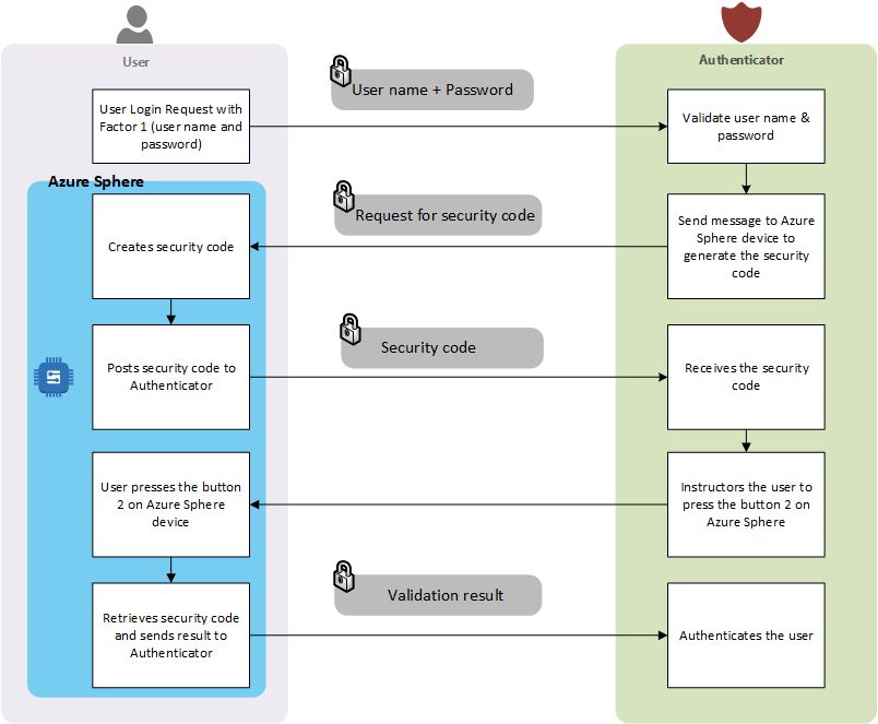
Let us start by taking a look at the high-level architecture design for presented in the post  Two-Factor authentication with Azure sphere and Azure IoT hub
Figure 1 - High-level architecture


Taking the high-level architecture forward, the evolved technical architecture is created as shown below:
Figure 2 - Technical Architecture

Before taking a detailed look at the technical architecture, let us start with looking at how the Authenticator application will work. This will give a good overview of what we are building (in terms of the end goal) and it will make it easier for us to understand the technical details.


User Interaction Flow

This sections illustrates the step by step interaction of user with the authenticator using screen shots.

1. Login page to initiate the first factor authentication
Figure 3 - Login screen

This step is quite simple. The above screen just carries out the first factor authentication.


2. User enters the user name and password for first factor authentication
Figure 4 - Login screen with user input


3. After successful first factor authentication, user is presented with a page to complete the second factor as show below:
Figure 5 - Second factor authentication screen showing status as "Pending"


4. As instructed in the Second factor authentication page, user presses the button "B" on the Azure Sphere device and the clicks the "Validate Second Factor" button on the screen.


5. As the result the authenticator validates the second factor and shows the authentication result as show below:
Figure 6 - Second factor authentication screen showing status as "true" (authenticated)

Now we have seen how the Authenticator application will look like and how it will interact with user, let delve into key components of the Two-Factor authentication using Azure Sphere and Azure IoT hub.

Key Components

User

User is initiator and the requester of the two factor authentication. It represents the user using a machine or device that is connected to Azure Sphere. The prerequisite section of the post Two-Factor authentication with Azure sphere and Azure IoT hub mentions the essential prerequisites for the user. 

Azure Sphere

This is the device that is attached to the user machine. It is responsible for second factor authentication. The request are received by the Azure Sphere by the Azure IoT hub and based on the request, it creates the security code that constitutes the essential part of the second factor authentication.

Authenticator

This represents the application that needs carries out the Two-Factor authentication. This can be a web app or an API. The authenticator acts as the controller of the Two-Factor authentication system by coordinating the calls that are requesting for first factor or second factor authentication. It talks to Azure Table Storage and sends requests in form of notifications to IoT hub when it needs to talk to Azure Sphere.

Azure IoT hub

Azure IoT hub is the central point of contact for requests and responses that are received to complete the second factor authentication. The Azure IoT hub receives the requests from the Azure Sphere device and forwards it as an event notification. The event notifications are then consumed by the Azure functions for processing. As mentioned in the prerequisite section of  Two-Factor authentication with Azure sphere and Azure IoT hub the Azure Sphere device has to be provisioned with Azure IoT hub.

Azure Table Storage

Azure table storage acts as the backing store for all the requests. When authenticator receives a requests, it creates a record in the TwoFactorRequest table which constitutes the Azure table storage. When Azure Sphere creates the security code, the security code is saved in the TwoFactorRequest table under the column "CreatedSecurityCode". When Azure Sphere retrieves the security code from its mutable memory, it is stored under the column "RetreivedSecurityCode". The authenticator uses these two columns to validate if the user has completed the second factor authentication or not.
Let us take a look at the structure of TwoFactorRequest Azure table storage.
Figure 7 - TwoFactorRequest table structure


Here is a quick view of the TwoFactoRequest table structure.
Figure 8 - Azure table storage quick view


Azure Function

There are two Azure Functions created for this solution. These are "Recorder" Azure function and "Validator" Azure function. The primary purpose of the these two Azure Functions is to receive notification for Azure IoT hub and post the results to Azure table storage in the TwoFactorRequest table. These Azure functions uses the built-in endpoints in Azure IoT hub to hook into event notifications. More detail on how to use built-in endpoints can be found on my previous blog post Leveraging Built-in endpoints in Azure IoT Hub
Although the architecture proposes to two use two separate function, we can use one function to be consumer of all the events and based on the request type, it can route to functions that will fulfill the tasks of either the "Recorder" or "Validator" functions. 

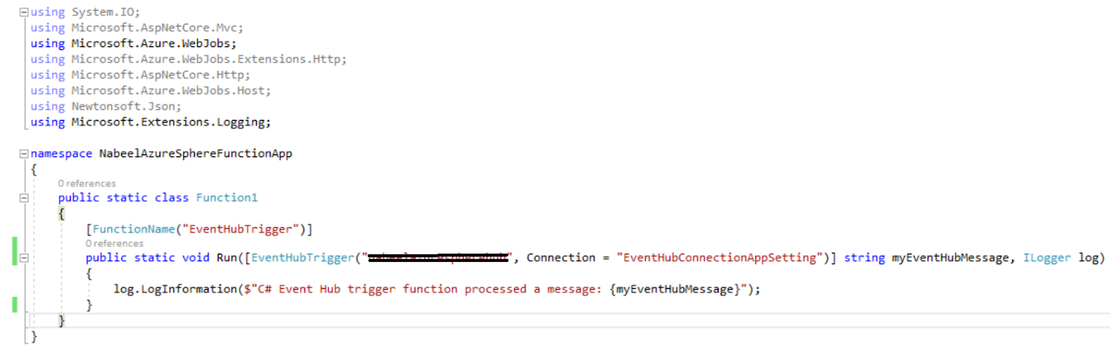
Here is the code snippet for the Azure function
using Framework.Services.Storage;
using Microsoft.Azure.WebJobs;
using Microsoft.Extensions.Configuration;
using Microsoft.Extensions.Logging;
using System.Configuration;
using TwoFactorAuthentication.Services.Contracts.Entities;
using IoTHubTrigger = Microsoft.Azure.WebJobs.EventHubTriggerAttribute;
/// <summary>
/// Captures messages coming into Azure IoT hub from Azure Sphere device.
/// </summary>
public static class DeviceMessageRecorderFunction
{
[FunctionName("EventHubTrigger")]
public static void Run([IoTHubTrigger("messages/events", Connection = "EventHubConnectionAppSetting")] string message, ILogger log, ExecutionContext context)
{
log.LogInformation($"IoT Hub trigger function processed a message: {message}");
SetEnvironment(context, log);
TableService tableService = new TableService();
if(message.Contains("|"))
{
var messageArray = message.Split("|");
// Check if the message is for retrieved security code or created security code. 5 means it is retrieved, 4 means it is created.
// Update data store for the created security code
if (messageArray.Length == 4)
{
var singleEntityTask = tableService.GetSingleEntityAsync<TwoFactorRequestEntity>("TwoFactorRequest", messageArray[0], messageArray[1]);
var retrievedEntity = singleEntityTask.Result;
retrievedEntity.CreatedSecurityCode = messageArray[3];
retrievedEntity.RequestCreationTimestamp = System.DateTime.Now.ToString();
var updateEntityTask = tableService.UpdateEntityAsync("TwoFactorRequest", retrievedEntity);
}
// Update data store for the retrieved (validated) security code
if (messageArray.Length == 5)
{
var singleEntityTask = tableService.GetSingleEntityAsync<TwoFactorRequestEntity>("TwoFactorRequest", messageArray[0], messageArray[1]);
var retrievedEntity = singleEntityTask.Result;
retrievedEntity.RetrievedSecurityCode = messageArray[3];
retrievedEntity.RequestValidatedTimestamp = System.DateTime.Now.ToString();
var updateEntityTask = tableService.UpdateEntityAsync("TwoFactorRequest", retrievedEntity);
}
}
}
}
}

Let us take a look at the code real quick. The Azure function is represented in form of static class called "DeviceMessageRecorderFunction". This class listens to event hub triggers by the user of its "Run" method. In the "Run" method the Azure Function looks at the message that it received from the Azure IoT hub. As mentioned the Azure IoT hub sends the event notification for two times. These are when the security code is created and when the security code is retrieved for validation. The Azure IoT sends these event notification messages as a result of being invoked by the Azure Sphere. For these two events, the message body is different. The message is "|" separated string.

When the security code is generated by the Azure Sphere it posts the message to Azure IoT hub in the following format.

Message format: userName|uniqueId|correlationId

Message example: admin|d6c28aef-8da6-4678-806d-2634b30266fc|e386a74be1ef4795a41432f2d59f8136

When the security code is retrieved for validation, the Azure Sphere sends the message to IoT hub in the following format

Message format: userName|uniqueId|correlationId|securityCode

Message example: admin|d6c28aef-8da6-4678-806d-2634b30266fc|e386a74be1ef4795a41432f2d59f8136|32322|retrieved

Going back to the "Run" method code, the code checks for the method type and based on its type it enters the data in the Azure table storage. This method takes care of both "Recorder" and "Validator" functionality.

Step by step flow

Let us take another look at the technical architecture:

Figure 9 - Technical Architecture

Let us take a look at the technical architecture in detail in terms of steps.

  1. The user sends the first factor authentication request in form of the user name and password as a secured post request.
  2. The authenticator validates the user name and password request thus completing the first factor authentication.
  3. In this step the authenticator creates a record in the TwoFactorRequest Azure table storage. It will have both "CreateSecurityCode" and "RetrievedSecurityCode" fields as null. This represents that a new request is going to go through the second factor authentication.
    Here is the code that that creates a new record in the TwoFactorRequest Azure table
    private async Task CreateTableAndAddRequest(string partitionKey, string rowKey, string correlationId)
    {
    var createTableTask = tableService.CreateTableAsync(RequestTable);
    TwoFactorRequestEntity tableEntity = new TwoFactorRequestEntity()
    {
    PartitionKey = partitionKey,
    RowKey = rowKey,
    CorrelationId = correlationId,
    RequestCreationTimestamp = DateTime.Now.ToString()
    };
    var insertResult = await tableService.InsertEntityAsync(RequestTable, tableEntity);
    }
  4. After creating a new request in TwoFactorRequest table, the authenticator sends a message to Azure IoT to request the Azure Sphere device to create a new "SecurityCode" using direct method to Azure Sphere.

    Here is the message format that is sent to Azure Sphere through Azure IoT.
    Message format: userName|uniqueId|correlationId

    Message example: admin|d6c28aef-8da6-4678-806d-2634b30266fc|e386a74be1ef4795a41432f2d59f8136

    Here is the code that invokes a direct method to Azure Sphere through Azure IoT:

    // Invoke the direct method on the device, passing the payload
    private async Task InvokeMethod(string userName, string uniqueId, string correlationId)
    {
    var methodInvocation = new CloudToDeviceMethod("LedColorControlMethod") { ResponseTimeout = TimeSpan.FromSeconds(30) };
    var dataString = $"{userName}|{uniqueId}|{correlationId}";
    var payLoadData = "{\"color\": \"red\", \"data\": \"" + dataString + "\"}";
    methodInvocation.SetPayloadJson(payLoadData);
    var deviceId = ConfigurationManager.AppSettings[DeviceIdConfigurationName];
    // Invoke the direct method asynchronously and get the response from the simulated device.
    var response = await serviceClient.InvokeDeviceMethodAsync(deviceId, methodInvocation);
    responseBody = response.GetPayloadAsJson();
    }
  5. As a result of the "DirectMethod" invocation, the Azure Sphere device generates a "Security Code" for second factor authentication. 
  6. Azure Sphere device then saves the created "Security Code" in its mutable memory and notifies the Azure IoT. The message that is sent to Azure IoT from Azure Sphere is show below:
    Message format: userName|uniqueId|correlationId|securityCode

    Message example: admin|d6c28aef-8da6-4678-806d-2634b30266fc|e386a74be1ef4795a41432f2d59f8136|2123

    In the above message the last segment "2123" represents the security code created
  7. Message is forwarded by the Azure IoT to Recorder function that is listening to events coming out of Azure IoT hub. The code mentioned in the section under "Azure Functions" takes care of that.
  8. The Azure function then updates the TwoFactorRequest table with the "SecurityCode" received from Azure Sphere through Azure IoT hub.
  9. As part of the Two-Factor authentication flow, the user has to press the button "B" on the Azure Sphere device. This ensures the user has access to the Azure Sphere device and the Azure Sphere device is properly provisioned with Azure IoT hub.
  10. Once user presses the button "B" on the Azure Sphere device, the Azure Sphere device retrieves the "Security Code" as the second factor from its mutable memory and posts it Azure IoT hub.
    For this step, the message that is sent to Azure IoT hub is in the following format:


    Message format: userName|uniqueId|correlationId|securityCode|retrieved


    Message example: admin|d6c28aef-8da6-4678-806d-2634b30266fc|e386a74be1ef4795a41432f2d59f8136|32322|retrieved
  11. The Azure IoT hub receives the retrieved message for validation and generates an event hub notification. This event hub notification is received by the Azure function. The code mentioned in the section under "Azure Functions" takes care of that.
  12. The Azure Function then validates that the security code that is retrieved is same when the first time Azure Sphere sent message as part of step 6.
  13. The Azure Function, then updates the TwoFactorRequest table with the retrieved "Security Code".

Once all the steps are completed and the security code is verified to be the same, the authenticator then notifies the user of successful authentication.


Azure Sphere's main.c code


#include <errno.h>
#include <signal.h>
#include <stdio.h>
#include <time.h>
#include <stdlib.h>
#include <stdbool.h>
#include <string.h>
#include <unistd.h>
// applibs_versions.h defines the API struct versions to use for applibs APIs.
#include "applibs_versions.h"
#include "epoll_timerfd_utilities.h"
#include <applibs/gpio.h>
#include <applibs/log.h>
#include <applibs/wificonfig.h>
#include <applibs/storage.h>
#include "mt3620_rdb.h"
#include "rgbled_utility.h"
// This sample C application for a MT3620 Reference Development Board (Azure Sphere) demonstrates how to
// connect an Azure Sphere device to an Azure IoT Hub. To use this sample, you must first
// add the Azure IoT Hub Connected Service reference to the project (right-click
// References -> Add Connected Service -> Azure IoT Hub), which populates this project
// with additional sample code used to communicate with an Azure IoT Hub.
//
// The sample leverages these functionalities of the Azure IoT SDK C:
// - Device to cloud messages;
// - Cloud to device messages;
// - Direct Method invocation;
// - Device Twin management;
//
// A description of the sample follows:
// - LED 1 blinks constantly.
// - Pressing button A toggles the rate at which LED 1 blinks
// between three values.
// - Pressing button B triggers the sending of a message to the IoT Hub.
// - LED 2 flashes red when button B is pressed (and a
// message is sent) and flashes yellow when a message is received.
// - LED 3 indicates whether network connection to the Azure IoT Hub has been
// established.
//
// Direct Method related notes:
// - Invoking the method named "LedColorControlMethod" with a payload containing '{"color":"red"}'
// will set the color of LED 1 to red;
//
// Device Twin related notes:
// - Setting LedBlinkRateProperty in the Device Twin to a value from 0 to 2 causes the sample to
// update the blink rate of LED 1 accordingly, e.g '{"LedBlinkRateProperty": 2}';
// - Upon receipt of the LedBlinkRateProperty desired value from the IoT hub, the sample updates
// the device twin on the IoT hub with the new value for LedBlinkRateProperty.
// - Pressing button A causes the sample to report the blink rate to the device
// twin on the IoT Hub.
// This sample uses the API for the following Azure Sphere application libraries:
// - gpio (digital input for button);
// - log (messages shown in Visual Studio's Device Output window during debugging);
// - wificonfig (configure WiFi settings);
// - azureiot (interaction with Azure IoT services)
#ifndef AZURE_IOT_HUB_CONFIGURED
#endif
#include "azure_iot_utilities.h"
// An array defining the RGB GPIOs for each LED on the device
static const GPIO_Id ledsPins[3][3] = {
{MT3620_RDB_LED1_RED, MT3620_RDB_LED1_GREEN, MT3620_RDB_LED1_BLUE}, {MT3620_RDB_LED2_RED, MT3620_RDB_LED2_GREEN, MT3620_RDB_LED2_BLUE}, {MT3620_RDB_LED3_RED, MT3620_RDB_LED3_GREEN, MT3620_RDB_LED3_BLUE}};
static size_t blinkIntervalIndex = 0;
static RgbLedUtility_Colors ledBlinkColor = RgbLedUtility_Colors_Blue;
static const struct timespec blinkIntervals[] = {{0, 125000000}, {0, 250000000}, {0, 500000000}};
static const size_t blinkIntervalsCount = sizeof(blinkIntervals) / sizeof(*blinkIntervals);
// File descriptors - initialized to invalid value
static int epollFd = -1;
static int gpioLedBlinkRateButtonFd = -1;
static int gpioSendMessageButtonFd = -1;
static int gpioButtonsManagementTimerFd = -1;
static int gpioLed1TimerFd = -1;
static int gpioLed2TimerFd = -1;
static int azureIotDoWorkTimerFd = -1;
// LED state
static RgbLed led1 = RGBLED_INIT_VALUE;
static RgbLed led2 = RGBLED_INIT_VALUE;
static RgbLed led3 = RGBLED_INIT_VALUE;
static RgbLed *rgbLeds[] = {&led1, &led2, &led3};
static const size_t rgbLedsCount = sizeof(rgbLeds) / sizeof(*rgbLeds);
// Default blinking rate of LED1
static struct timespec blinkingLedPeriod = {0, 125000000};
static bool blinkingLedState;
// A null period to not start the timer when it is created with CreateTimerFdAndAddToEpoll.
static const struct timespec nullPeriod = {0, 0};
static const struct timespec defaultBlinkTimeLed2 = {0, 150 * 1000 * 1000};
// Connectivity state
static bool connectedToIoTHub = false;
// Termination state
static volatile sig_atomic_t terminationRequired = false;
/// <summary>
/// Signal handler for termination requests. This handler must be async-signal-safe.
/// </summary>
static void TerminationHandler(int signalNumber)
{
// Don't use Log_Debug here, as it is not guaranteed to be async-signal-safe.
terminationRequired = true;
}
/// <summary>
/// Show details of the currently connected WiFi network.
/// </summary>
static void DebugPrintCurrentlyConnectedWiFiNetwork(void)
{
WifiConfig_ConnectedNetwork network;
int result = WifiConfig_GetCurrentNetwork(&network);
if (result < 0) {
Log_Debug("INFO: Not currently connected to a WiFi network.\n");
} else {
Log_Debug("INFO: Currently connected WiFi network: \n");
Log_Debug("INFO: SSID \"%.*s\", BSSID %02x:%02x:%02x:%02x:%02x:%02x, Frequency %dMHz.\n",
network.ssidLength, network.ssid, network.bssid[0], network.bssid[1],
network.bssid[2], network.bssid[3], network.bssid[4], network.bssid[5],
network.frequencyMHz);
}
}
/// <summary>
/// Helper function to blink LED2 once.
/// </summary>
static void BlinkLed2Once(void)
{
RgbLedUtility_SetLed(&led2, RgbLedUtility_Colors_Red);
SetTimerFdToSingleExpiry(gpioLed2TimerFd, &defaultBlinkTimeLed2);
}
/// <summary>
/// Helper function to open a file descriptor for the given GPIO as input mode.
/// </summary>
/// <param name="gpioId">The GPIO to open.</param>
/// <param name="outGpioFd">File descriptor of the opened GPIO.</param>
/// <returns>True if successful, false if an error occurred.</return>
static bool OpenGpioFdAsInput(GPIO_Id gpioId, int *outGpioFd)
{
*outGpioFd = GPIO_OpenAsInput(gpioId);
if (*outGpioFd < 0) {
Log_Debug("ERROR: Could not open GPIO '%d': %d (%s).\n", gpioId, errno, strerror(errno));
return false;
}
return true;
}
/// <summary>
/// Toggles the blink speed of the blink LED between 3 values, and updates the device twin.
/// </summary>
/// <param name="rate">The blink rate</param>
static void SetLedRate(const struct timespec *rate)
{
if (SetTimerFdToPeriod(gpioLed1TimerFd, rate) != 0) {
Log_Debug("ERROR: could not set the period of the LED.\n");
terminationRequired = true;
return;
}
if (connectedToIoTHub) {
// Report the current state to the Device Twin on the IoT Hub.
AzureIoT_TwinReportState("LedBlinkRateProperty", blinkIntervalIndex);
} else {
Log_Debug("WARNING: Cannot send reported property; not connected to the IoT Hub.\n");
}
}
/// <summary>
/// Sends a message to the IoT Hub.
/// </summary>
static void SendMessageToIotHub(void)
{
if (connectedToIoTHub) {
// char *readValue = ReadMutableFile();
int fd = Storage_OpenMutableFile();
if (fd < 0) {
Log_Debug("ERROR: Could not open mutable file: %s (%d).\n", strerror(errno), errno);
return -1;
}
char *value;
ssize_t ret = read(fd, &value, sizeof(value));
if (ret < 0) {
Log_Debug("ERROR: An error occurred while reading file: %s (%d).\n", strerror(errno), errno);
}
close(fd);
if (ret < sizeof(value)) {
return 0;
}
// Send a message
strcat(value, "|retreived");
AzureIoT_SendMessage(value);
// Set the send/receive LED2 to blink once immediately to indicate the message has been
// queued.
BlinkLed2Once();
} else {
Log_Debug("WARNING: Cannot send message: not connected to the IoT Hub.\n");
}
}
/// <summary>
/// Write an integer to this application's persistent data file
/// </summary>
static void WriteToMutableFile(char *value) {
int fd = Storage_OpenMutableFile();
if (fd < 0) {
Log_Debug("ERROR: Could not open mutable file: %s (%d).\n", strerror(errno), errno);
return;
}
ssize_t ret = write(fd, &value, sizeof(value));
if (ret < 0) {
// If the file has reached the maximum size specified in the application manifest,
// then -1 will be returned with errno EDQUOT (122)
Log_Debug("ERROR: An error occurred while writing to mutable file: %s (%d).\n",
strerror(errno), errno);
}
else if (ret < sizeof(value)) {
// For simplicity, this sample logs an error here. In the general case, this should be
// handled by retrying the write with the remaining data until all the data has been written.
Log_Debug("ERROR: Only wrote %d of %d bytes requested\n", ret, (int)sizeof(value));
}
close(fd);
}
/// <summary>
/// Read an integer from this application's persistent data file
/// </summary>
/// <returns>
/// The integer that was read from the file. If the file is empty, this returns 0. If the storage
/// API fails, this returns -1.
/// </returns>
static char * ReadMutableFile(void) {
int fd = Storage_OpenMutableFile();
if (fd < 0) {
Log_Debug("ERROR: Could not open mutable file: %s (%d).\n", strerror(errno), errno);
return -1;
}
char *value;
ssize_t ret = read(fd, &value, sizeof(value));
if (ret < 0) {
Log_Debug("ERROR: An error occurred while reading file: %s (%d).\n", strerror(errno), errno);
}
close(fd);
if (ret < sizeof(value)) {
return 0;
}
return value;
}
/// <summary>
/// Sends a message to the IoT Hub.
/// </summary>
static void SendMessageToIotHubAsResultOfLedCall(void)
{
if (connectedToIoTHub) {
// Send a message
WriteToMutableFile("7757");
char *readValue = ReadMutableFile();
AzureIoT_SendMessage("7757");
// Set the send/receive LED2 to blink once immediately to indicate the message has been
// queued.
BlinkLed2Once();
}
else {
Log_Debug("WARNING: Cannot send message: not connected to the IoT Hub.\n");
}
}
/// <summary>
/// Sends a message to the IoT Hub.
/// </summary>
static void SendMessageToIotHubAsResultOfLedCallWithData(char *data)
{
if (connectedToIoTHub) {
// Send a message
WriteToMutableFile(data);
char *readValue = ReadMutableFile();
AzureIoT_SendMessage(readValue);
// Set the send/receive LED2 to blink once immediately to indicate the message has been
// queued.
BlinkLed2Once();
}
else {
Log_Debug("WARNING: Cannot send message: not connected to the IoT Hub.\n");
}
}
/// <summary>
/// MessageReceived callback function, called when a message is received from the Azure IoT Hub.
/// </summary>
/// <param name="payload">The payload of the received message.</param>
static void MessageReceived(const char *payload)
{
// Set the send/receive LED2 to blink once immediately to indicate a message has been received.
BlinkLed2Once();
}
/// <summary>
/// Device Twin update callback function, called when an update is received from the Azure IoT
/// Hub.
/// </summary>
/// <param name="desiredProperties">The JSON root object containing the desired Device Twin
/// properties received from the Azure IoT Hub.</param>
static void DeviceTwinUpdate(JSON_Object *desiredProperties)
{
JSON_Value *blinkRateJson = json_object_get_value(desiredProperties, "LedBlinkRateProperty");
// If the attribute is missing or its type is not a number.
if (blinkRateJson == NULL) {
Log_Debug(
"INFO: A device twin update was received that did not contain the property "
"\"LedBlinkRateProperty\".\n");
} else if (json_value_get_type(blinkRateJson) != JSONNumber) {
Log_Debug(
"INFO: Device twin desired property \"LedBlinkRateProperty\" was received with "
"incorrect type; it must be an integer.\n");
} else {
// Get the value of the LedBlinkRateProperty and print it.
size_t desiredBlinkRate = (size_t)json_value_get_number(blinkRateJson);
blinkIntervalIndex =
desiredBlinkRate % blinkIntervalsCount; // Clamp value to [0..blinkIntervalsCount) .
Log_Debug("INFO: Received desired value %zu for LedBlinkRateProperty, setting it to %zu.\n",
desiredBlinkRate, blinkIntervalIndex);
blinkingLedPeriod = blinkIntervals[blinkIntervalIndex];
SetLedRate(&blinkIntervals[blinkIntervalIndex]);
}
}
/// <summary>
/// Allocates and formats a string message on the heap.
/// </summary>
/// <param name="messageFormat">The format of the message</param>
/// <param name="maxLength">The maximum length of the formatted message string</param>
/// <returns>The pointer to the heap allocated memory.</returns>
static void *SetupHeapMessage(const char *messageFormat, size_t maxLength, ...)
{
va_list args;
va_start(args, maxLength);
char *message =
malloc(maxLength + 1); // Ensure there is space for the null terminator put by vsnprintf.
if (message != NULL) {
vsnprintf(message, maxLength, messageFormat, args);
}
va_end(args);
return message;
}
/// <summary>
/// Direct Method callback function, called when a Direct Method call is received from the Azure
/// IoT Hub.
/// </summary>
/// <param name="methodName">The name of the method being called.</param>
/// <param name="payload">The payload of the method.</param>
/// <param name="responsePayload">The response payload content. This must be a heap-allocated
/// string, 'free' will be called on this buffer by the Azure IoT Hub SDK.</param>
/// <param name="responsePayloadSize">The size of the response payload content.</param>
/// <returns>200 HTTP status code if the method name is "LedColorControlMethod" and the color is
/// correctly parsed;
/// 400 HTTP status code is the color has not been recognised in the payload;
/// 404 HTTP status code if the method name is unknown.</returns>
static int DirectMethodCall(const char *methodName, const char *payload, size_t payloadSize,
char **responsePayload, size_t *responsePayloadSize)
{
// Prepare the payload for the response. This is a heap allocated null terminated string.
// The Azure IoT Hub SDK is responsible of freeing it.
*responsePayload = NULL; // Reponse payload content.
*responsePayloadSize = 0; // Response payload content size.
int result = 404; // HTTP status code.
if (strcmp(methodName, "LedColorControlMethod") != 0) {
result = 404;
Log_Debug("INFO: Method not found called: '%s'.\n", methodName);
static const char noMethodFound[] = "\"method not found '%s'\"";
size_t responseMaxLength = sizeof(noMethodFound) + strlen(methodName);
*responsePayload = SetupHeapMessage(noMethodFound, responseMaxLength, methodName);
if (*responsePayload == NULL) {
Log_Debug("ERROR: Could not allocate buffer for direct method response payload.\n");
abort();
}
*responsePayloadSize = strlen(*responsePayload);
return result;
}
RgbLedUtility_Colors ledColor = RgbLedUtility_Colors_Unknown;
// The payload should contains JSON such as: { "color": "red"}
char *directMethodCallContent = malloc(payloadSize + 1); // +1 to store null char at the end.
if (directMethodCallContent == NULL) {
Log_Debug("ERROR: Could not allocate buffer for direct method request payload.\n");
abort();
}
memcpy(directMethodCallContent, payload, payloadSize);
directMethodCallContent[payloadSize] = 0; // Null terminated string.
JSON_Value *payloadJson = json_parse_string(directMethodCallContent);
if (payloadJson == NULL) {
goto colorNotFound;
}
JSON_Object *colorJson = json_value_get_object(payloadJson);
if (colorJson == NULL) {
goto colorNotFound;
}
const char *colorName = json_object_get_string(colorJson, "color");
if (colorName == NULL) {
goto colorNotFound;
}
// Getting data portion out
JSON_Object *dataJson = json_value_get_object(payloadJson);
if (dataJson == NULL) {
goto dataNotFound;
}
const char *dataValue = json_object_get_string(dataJson, "data");
if (dataValue == NULL) {
goto dataNotFound;
}
int securityCode = 1000 + (rand() % 9000);
char buffer[4];
sprintf(buffer, "%d", securityCode);
//strcat(output, buffer);
//char *dataValueWithSecurityCode = strcat(dataValue + '|', output);
char *dataValueWithSecurityCode = strcat(dataValue, "");
strcat(dataValueWithSecurityCode, "|");
strcat(dataValueWithSecurityCode, &buffer[0]);
ledColor = RgbLedUtility_GetColorFromString(colorName, strlen(colorName));
// If color's name has not been identified.
if (ledColor == RgbLedUtility_Colors_Unknown) {
goto colorNotFound;
}
// Color's name has been identified.
result = 200;
const char *colorString = RgbLedUtility_GetStringFromColor(ledColor);
Log_Debug("INFO: LED color set to: '%s'.\n", colorString);
// Set the blinking LED color.
ledBlinkColor = ledColor;
static const char colorOkResponse[] =
"{ \"success\" : true, \"message\" : \"led color set to %s\" }";
size_t responseMaxLength = sizeof(colorOkResponse) + strlen(payload);
*responsePayload = SetupHeapMessage(colorOkResponse, responseMaxLength, colorString);
if (*responsePayload == NULL) {
Log_Debug("ERROR: Could not allocate buffer for direct method response payload.\n");
abort();
}
*responsePayloadSize = strlen(*responsePayload);
if (dataValue == NULL) {
SendMessageToIotHubAsResultOfLedCall();
}
else
{
SendMessageToIotHubAsResultOfLedCallWithData(dataValueWithSecurityCode);
}
return result;
colorNotFound:
result = 400; // Bad request.
Log_Debug("INFO: Unrecognised direct method payload format.\n");
static const char noColorResponse[] =
"{ \"success\" : false, \"message\" : \"request does not contain an identifiable "
"color\" }";
responseMaxLength = sizeof(noColorResponse);
*responsePayload = SetupHeapMessage(noColorResponse, responseMaxLength);
if (*responsePayload == NULL) {
Log_Debug("ERROR: Could not allocate buffer for direct method response payload.\n");
abort();
}
*responsePayloadSize = strlen(*responsePayload);
return result;
dataNotFound:
result = 200; // Bad request.
Log_Debug("INFO: No data given in the payload.\n");
return result;
}
/// <summary>
/// IoT Hub connection status callback function.
/// </summary>
/// <param name="connected">'true' when the connection to the IoT Hub is established.</param>
static void IoTHubConnectionStatusChanged(bool connected)
{
connectedToIoTHub = connected;
}
/// <summary>
/// Handle the blinking for LED1.
/// </summary>
static void Led1UpdateHandler(event_data_t *eventData)
{
if (ConsumeTimerFdEvent(gpioLed1TimerFd) != 0) {
terminationRequired = true;
return;
}
// Set network status with LED3 color.
RgbLedUtility_Colors color =
(connectedToIoTHub ? RgbLedUtility_Colors_Green : RgbLedUtility_Colors_Off);
RgbLedUtility_SetLed(&led3, color);
// Trigger LED to blink as appropriate.
blinkingLedState = !blinkingLedState;
color = (blinkingLedState ? ledBlinkColor : RgbLedUtility_Colors_Off);
RgbLedUtility_SetLed(&led1, color);
}
/// <summary>
/// Handle the blinking for LED2.
/// </summary>
static void Led2UpdateHandler(event_data_t *eventData)
{
if (ConsumeTimerFdEvent(gpioLed2TimerFd) != 0) {
terminationRequired = true;
return;
}
// Clear the send/receive LED2.
RgbLedUtility_SetLed(&led2, RgbLedUtility_Colors_Off);
}
/// <summary>
/// Check whether a given button has just been pressed.
/// </summary>
/// <param name="fd">The button file descriptor</param>
/// <param name="oldState">Old state of the button (pressed or released)</param>
/// <returns>true if pressed, false otherwise</returns>
static bool IsButtonPressed(int fd, GPIO_Value_Type *oldState)
{
bool isButtonPressed = false;
GPIO_Value_Type newState;
int result = GPIO_GetValue(fd, &newState);
if (result != 0) {
Log_Debug("ERROR: Could not read button GPIO: %s (%d).\n", strerror(errno), errno);
terminationRequired = true;
} else {
// Button is pressed if it is low and different than last known state.
isButtonPressed = (newState != *oldState) && (newState == GPIO_Value_Low);
*oldState = newState;
}
return isButtonPressed;
}
/// <summary>
/// Handle button timer event: if the button is pressed, change the LED blink rate.
/// </summary>
static void ButtonsHandler(event_data_t *eventData)
{
if (ConsumeTimerFdEvent(gpioButtonsManagementTimerFd) != 0) {
terminationRequired = true;
return;
}
// If the button is pressed, change the LED blink interval, and update the Twin Device.
static GPIO_Value_Type blinkButtonState;
if (IsButtonPressed(gpioLedBlinkRateButtonFd, &blinkButtonState)) {
blinkIntervalIndex = (blinkIntervalIndex + 1) % blinkIntervalsCount;
SetLedRate(&blinkIntervals[blinkIntervalIndex]);
}
// If the button is pressed, send a message to the IoT Hub.
static GPIO_Value_Type messageButtonState;
if (IsButtonPressed(gpioSendMessageButtonFd, &messageButtonState)) {
SendMessageToIotHub();
}
}
/// <summary>
/// Hand over control periodically to the Azure IoT SDK's DoWork.
/// </summary>
static void AzureIotDoWorkHandler(event_data_t *eventData)
{
if (ConsumeTimerFdEvent(azureIotDoWorkTimerFd) != 0) {
terminationRequired = true;
return;
}
// Set up the connection to the IoT Hub client.
// Notes it is safe to call this function even if the client has already been set up, as in
// this case it would have no effect
if (AzureIoT_SetupClient()) {
// AzureIoT_DoPeriodicTasks() needs to be called frequently in order to keep active
// the flow of data with the Azure IoT Hub
AzureIoT_DoPeriodicTasks();
}
}
// event handler data structures. Only the event handler field needs to be populated.
static event_data_t buttonsEventData = {.eventHandler = &ButtonsHandler};
static event_data_t led1EventData = {.eventHandler = &Led1UpdateHandler};
static event_data_t led2EventData = {.eventHandler = &Led2UpdateHandler};
static event_data_t azureIotEventData = {.eventHandler = &AzureIotDoWorkHandler};
/// <summary>
/// Initialize peripherals, termination handler, and Azure IoT
/// </summary>
/// <returns>0 on success, or -1 on failure</returns>
static int InitPeripheralsAndHandlers(void)
{
// Register a SIGTERM handler for termination requests
struct sigaction action;
memset(&action, 0, sizeof(struct sigaction));
action.sa_handler = TerminationHandler;
sigaction(SIGTERM, &action, NULL);
// Open button A
Log_Debug("INFO: Opening MT3620_RDB_BUTTON_A.\n");
if (!OpenGpioFdAsInput(MT3620_RDB_BUTTON_A, &gpioLedBlinkRateButtonFd)) {
return -1;
}
// Open button B
Log_Debug("INFO: Opening MT3620_RDB_BUTTON_B.\n");
if (!OpenGpioFdAsInput(MT3620_RDB_BUTTON_B, &gpioSendMessageButtonFd)) {
return -1;
}
// Open file descriptors for the RGB LEDs and store them in the rgbLeds array (and in turn in
// the ledBlink, ledMessageEventSentReceived, ledNetworkStatus variables)
RgbLedUtility_OpenLeds(rgbLeds, rgbLedsCount, ledsPins);
// Initialize the Azure IoT SDK
if (!AzureIoT_Initialize()) {
Log_Debug("ERROR: Cannot initialize Azure IoT Hub SDK.\n");
return -1;
}
// Set the Azure IoT hub related callbacks
AzureIoT_SetMessageReceivedCallback(&MessageReceived);
AzureIoT_SetDeviceTwinUpdateCallback(&DeviceTwinUpdate);
AzureIoT_SetDirectMethodCallback(&DirectMethodCall);
AzureIoT_SetConnectionStatusCallback(&IoTHubConnectionStatusChanged);
// Display the currently connected WiFi connection.
DebugPrintCurrentlyConnectedWiFiNetwork();
epollFd = CreateEpollFd();
if (epollFd < 0) {
return -1;
}
// Set up a timer for LED1 blinking
gpioLed1TimerFd =
CreateTimerFdAndAddToEpoll(epollFd, &blinkingLedPeriod, &led1EventData, EPOLLIN);
if (gpioLed1TimerFd < 0) {
return -1;
}
// Set up a timer for blinking LED2 once.
gpioLed2TimerFd = CreateTimerFdAndAddToEpoll(epollFd, &nullPeriod, &led2EventData, EPOLLIN);
if (gpioLed2TimerFd < 0) {
return -1;
}
// Set up a timer for buttons status check
static struct timespec buttonsPressCheckPeriod = {0, 1000000};
gpioButtonsManagementTimerFd =
CreateTimerFdAndAddToEpoll(epollFd, &buttonsPressCheckPeriod, &buttonsEventData, EPOLLIN);
if (gpioButtonsManagementTimerFd < 0) {
return -1;
}
// Set up a timer for Azure IoT SDK DoWork execution.
static struct timespec azureIotDoWorkPeriod = {1, 0};
azureIotDoWorkTimerFd =
CreateTimerFdAndAddToEpoll(epollFd, &azureIotDoWorkPeriod, &azureIotEventData, EPOLLIN);
if (azureIotDoWorkTimerFd < 0) {
return -1;
}
return 0;
}
/// <summary>
/// Close peripherals and Azure IoT
/// </summary>
static void ClosePeripheralsAndHandlers(void)
{
Log_Debug("INFO: Closing GPIOs and Azure IoT client.\n");
// Close all file descriptors
CloseFdAndPrintError(gpioLedBlinkRateButtonFd, "LedBlinkRateButton");
CloseFdAndPrintError(gpioSendMessageButtonFd, "SendMessageButton");
CloseFdAndPrintError(gpioButtonsManagementTimerFd, "ButtonsManagementTimer");
CloseFdAndPrintError(azureIotDoWorkTimerFd, "IotDoWorkTimer");
CloseFdAndPrintError(gpioLed1TimerFd, "Led1Timer");
CloseFdAndPrintError(gpioLed2TimerFd, "Led2Timer");
CloseFdAndPrintError(epollFd, "Epoll");
// Close the LEDs and leave then off
RgbLedUtility_CloseLeds(rgbLeds, rgbLedsCount);
// Destroy the IoT Hub client
AzureIoT_DestroyClient();
AzureIoT_Deinitialize();
}
/// <summary>
/// Main entry point for this application.
/// </summary>
int main(int argc, char *argv[])
{
Log_Debug("INFO: Azure IoT application starting.\n");
int initResult = InitPeripheralsAndHandlers();
if (initResult != 0) {
terminationRequired = true;
}
while (!terminationRequired) {
if (WaitForEventAndCallHandler(epollFd) != 0) {
terminationRequired = true;
}
}
ClosePeripheralsAndHandlers();
Log_Debug("INFO: Application exiting.\n");
return 0;
}
view raw main.c hosted with ❤ by GitHub

Conclusion

In this blog post, we have seen how to implement Two-Factor authentication using Azure Sphere and Azure IoT hub. We have started off with the user interaction screens to have an overview of what we are building. Then we looked deeply in each key component of this system. After that the steps help us explain the technical architecture in detail.

If you have any questions or need any details on part of this implementation, please feel free to contact me at: mnabeelkhan@gmail.com


Friday, December 7, 2018

How to read appSettings JSON from Class Library in ASP.NET Core without modifying the Class Library

Back story

I recently ran into an issue where I needed to read the settings from ASP.NET Core app into a Class Library project. Since I was creating the ASP.NET Core, I had the access to the source code. But the class library was already written and I had no access to source code and hence any change that I was suppose to do had to be done in the ASP.NET Core app.


I looked for solution and found one here : https://corderoski.wordpress.com/2017/09/18/how-to-read-appsettings-json-from-class-library-in-asp-net-core/

The solution was great as long as you have the ability to change both the ASP.NET Core app and the Class Library. Since I did not have the access to source code for the Class Library, I could not use that solution.

So I came up with following solution.

Solution


On the constructor of the ASP.NET Core app, I added the following code:

        public MyController(IConfiguration configuration)
        {
            this.configuration = configuration;
            var configFile = ConfigurationManager.OpenExeConfiguration(ConfigurationUserLevel.None);
            var settings = configFile.AppSettings.Settings;
            configFile.Save(ConfigurationSaveMode.Modified);
            ConfigurationManager.RefreshSection(configFile.AppSettings.SectionInformation.Name);

            // Remove previous settings to ensure new settings are applied.
            if(settings[Settings1Key] != null)
            {
                settings.Remove(Settings1Key);
            }
            if (settings[Settings2Key] != null)
            {
                settings.Remove(Settings2Key);
            }
            if (settings[Settings3Key] != null)
            {
                settings.Remove(Settings3Key);
            }

            settings.Add("Settings1Key", this.configuration["Settings1Key"]);
            settings.Add("Settings2Key", this.configuration["Settings2Key"]);
            settings.Add("Settings3Key", this.configuration["Settings3Key"]);
            configFile.Save(ConfigurationSaveMode.Modified);
            ConfigurationManager.RefreshSection(configFile.AppSettings.SectionInformation.Name);
        }

Here the code change that I made to the Startup.cs file in the ASP.NET Core app:


        public void ConfigureServices(IServiceCollection services)
        {
            services.Configure(options =>
            {
                // This lambda determines whether user consent for non-essential cookies is needed for a given request.
                options.CheckConsentNeeded = context => true;
                options.MinimumSameSitePolicy = SameSiteMode.None;
            });

            services.AddMvc().SetCompatibilityVersion(CompatibilityVersion.Version_2_1);
            services.AddSingleton(Configuration);
        }


That is it. What we have done here is that we pulled the settings from the appsettings.json file on run time and modified the ConfigurationManager on runtime and saved it. Now when the Class Library is called, it had the access to the configuration that it was looking for.

Happy coding!


Tuesday, December 4, 2018

Two-Factor authentication with Azure sphere and Azure IoT hub

Introduction

This blog post introduces to a new way of carrying out two factor authentication using Azure Sphere. As more and more devices are being added to IoT world, there has been increasing need for a device that is secure and connects to Azure IoT to further automate the process. Azure Sphere fills that gap of secure communication. More information on Azure Sphere can be found at: https://azure.microsoft.com/en-us/blog/introducing-microsoft-azure-sphere-secure-and-power-the-intelligent-edge/

The intended goal of this blog post is to present a use of Azure Sphere. The best way to understand any technology is by creating a product or use that shows how the technology works and how it can be leveraged. This blog post presents a use of Azure Sphere by introducing a way to implement "Two factor authentication".

Information on how to setup Azure Sphere can be found in my previous blog post at: Getting started with Azure Sphere


Disclaimers

The information provided in this blog is intended to demonstrate a novel use of Azure Sphere. It does not recommend the "Azure Sphere based two factor Authentication" be used in production environment. The recommendation is to use the material provided in this blog as an opportunity to learn and understand Azure Sphere and Azure IoT.

Typical two factor authentication

Let us start by looking a typical two factor authentication. In traditional two factor authentication, a user (using a supported device like, smart phone, desktop or tablet), initiates the authentication by providing a user name and password to the authentication provider. Typically an authentication provider is the system that is part of a web site or an application. The authentication provider takes the user name and password and authenticates the user. This user of user name and password constitutes the first factor of the authentication. On successful authentication of the first factor (user name and password), the authentication provider sends a code to device that is associated with the user who is requesting the authentication. Typically the code sent through text or a phone call. The user receives the code. The authentication provider then provides a page for the user to enter the code that is sent. This code constitutes what we call the second factor. On receiving the second factor (code) the authentication provider verifies the code and completes the authentication process. 
Following diagram illustrates the typical two factor authentication flow.

Figure 1 - Typical two factor authentication flow

Two-Factor Authentication using Azure Sphere

The Two-Factor Authentication using Azure Sphere uses the same authentication mechanism for the first factor (i.e. username and password). But for the second factor it leverages the Azure Sphere device. The Azure Sphere device is attached to a device that is being used by the user requesting the authentication. This replaces the need to have the authentication provider send a code to a user device (such as phone for text message). Instead it relies on the Azure Sphere attached a users device to carryout the second factor authentication. The Azure Sphere device is connected to Azure IoT and that communication is secured by design.
The inspiration of using Azure Sphere as the second factor authentication device came from a paper called "The Seven Properties of Highly Secure Devices" published by Galen Hunt, George Letey, and Edmund B. Nightingale of Microsoft Research. Here is the link for that paper: https://www.microsoft.com/en-us/research/wp-content/uploads/2017/03/SevenPropertiesofHighlySecureDevices.pdf

Why use Azure Sphere for second factor authentication


  1. Hardware based security. As mentioned in the "The Seven Properties of Highly Secure Devices" paper, the "Highly secure devices have a hardware-based root of trust." Here is the excerpt from that paper.
    Highly secure devices have a hardware-based root of trust. Device secrets are protected by hardware and the hardware contains physical countermeasures against side-channel attacks. Unlike software, hardware has two important properties that may be used to establish device security. First, single purpose hardware is immune to reuse by an attacker for unintended actions. Second, hardware can detect and mitigate against physical attacks; for example, pulse testing the reset pin to prevent glitching attacks is easily implemented in hardware. When used to protect secrets and device correctness, hardware provides a solid root of trust upon which rich software functionality can be implemented securely and safely. 
  2. Secured Communication: The communication between the Azure Sphere device and Azure IoT hub is secured by Azure. As system implementor we would not need to secure the communication as we are leverage Azure for that. 

Prerequisites

  1. Since Two-Factor Authentication using Azure Sphere is based on Azure Sphere device connected to user's machine, it is important to mention that the prerequisite of this system is to have Azure Sphere device properly connected the user's machine. Information on setting up Azure Sphere device with a machine is provide in previous blog post Getting started with Azure Sphere
  2. The second prerequisite is to make sure the Azure Sphere device has been added to an Azure IoT hub. More information for that can be found at Microsoft Docs article Set up an IoT Hub for Azure Sphere

Authentication Flow with Azure Sphere

As mentioned above the first step is validating the factor 1 which is typical user name and password authentication. The following steps illustrates the flow information and authentication mechanism for the factor 2 (security code):
  1. User provides the user name and password that is passed on to the authenticator (authentication provider). 
  2. The authenticator validates the user name and password thus completing the factor 1 authentication. 
  3. After that authenticator sends message to Azure Sphere device attached to the user's machine to generate a security code and instructs the user to press the Button 2 on the Azure Sphere device. Information on setting up Azure Sphere device is provide in prerequisite section mentioned above. 
  4. The Azure Sphere device receives the request through its connection to Azure IoT hub. 
  5. It then generates a security code, saves the security code in its mutable memory and posts the result to Azure IoT hub. 
  6. Azure IoT hub informs the authenticator (authentication provider) about the generated security code. 
  7. As instructed by the authenticator, the user presses the Button 2 on the Azure Sphere device. 
  8. The Azure Sphere device retrieves the saved security code and posts the information to Azure IoT hub. 
  9. The authenticator then receives the notification that user has pressed the Button 2 along with the security code that was retrieved by the Azure Sphere device from its mutable memory. 
  10. The authenticator then validates the security code retrieved previously when Azure Sphere generated the security code and when the Button 2 was pressed. 
  11. Based on the authentication result, the user is deemed authenticated or not.

Figure 2 - Two Factor Authentication using Azure Sphere


Conclusion

Although Azure Sphere is quite powerful and versatile, we have seen how we can leverage Azure Sphere and Azure IoT hub to provide the second factor authentication for a two-factor authentication system. There are other systems that can be build on top of the design that is presented here. If we look further, we can connect another device with Azure Sphere device that provide other uses. For example, we can provide a display to show the security code that is generated by the Azure Sphere device that can be entered into an interface provider by the authenticator.

In my next blog post, I have taken provided technical details on how Two-Factor authentication is implemented using Azure Sphere and Azure IoT hub. The details are provider at: Two-Factor authentication with Azure sphere and Azure IoT hub - Step by step

Comments are welcome.


Sunday, November 25, 2018

Leveraging Built-in endpoints in Azure IoT Hub

Introduction


One of the great features of IoT hub is its built-in systems endpoints. This allows us to quickly hook into event hub belonging to an IoT hub without the need to an EventHub, Azure Storage containers, Service Bus queues and Service Bus topics.

In this post, we are going to look into how to easily we can leverage the built-in endpoints in Azure IoT hub by creating a simple application using Azure Functions.

When you have an Azure IoT hub and want to hook into events generated by Azure IoT hub, you have two main choices.

1. Events provided as part of Azure Event Grid
Using Azure Event Grid we can use resources such as Logic Apps, Azure Functions, Web Hook, Storage Queues, Event Hubs, and Hybrid Connections.

2. Built-in endpoints

This is the built in endpoint that every Azure IoT hub offers as part of its infrastructure. Using Built-in endpoints we can hook into system and device messages. So when a device sends a message to Azure IoT hub, this "Built-in endpoints" to receive those messages.

Figure 1 - Built-in endpoints view

Using Built-in endpoints

To use built-in endpoints, we will create a custom Azure functions that uses the built-in endpoint to listen to messages emitted by the device to Azure IoT hub. We will  use the following steps to accomplish that.

Step 1- Get Event Hub-compatible endpoint

  1. Open the Azure portal and navigate to Azure IoT hub. 
  2. Click "Built-in endpoints" in the navigation pane. This will show a view that is similar to view show in Figure 1.
  3. Copy "Event Hub-compatible endpoint" and save it to be used in the Azure Function app that is mentioned in Step 2.

Step 2 - Creating Azure Function App

1. Using the boiler plate project that is created when Azure Function App is selected, we can modify the code  as shown below.
Figure 2 - Azure function code

2. Update connection string:
Using the connection string saved in Step 1, update the local.settings.json as shown below:
Figure 3 - Event hub connection string using Built-in endpoint


3. Managing dependencies:
In order to use the Event Hub triggers, we have to add the following NuGet packages:
Figure 4 - Dependencies


Conclusion

We have seen how easy it is to use Built-in endpoints to hook into  Azure IoT hub events. Although we have used Azure Functions app to demonstrate the application that is listening to Azure IoT events using Built-In endpoints, we can use any application platform that can be invoked using EventHubTrigger.

Thursday, November 1, 2018

Getting started with Azure Sphere

Azure Sphere - MT 3620 on my work desk


Note: This is first of a series of blog posts that are related to my work done on Azure Sphere. Stay tuned for more on Azure Sphere.

Introduction

One of the best to learn a new technology is to just get hands dirty start work on the new technology. In this blog,  I will take you through the steps that I carried out in order to start work on Azure Sphere.

Once you have received the Azure Sphere device, it's time to get started. Here is the link https://azure.microsoft.com/en-us/services/azure-sphere/get-started/that will take you through the steps of acquiring a Azure Sphere device.

1. The very step is to attached the device with your development machine. If you have the correct operating system then the device manager should automatically install the drivers. In my case the drivers for the device did not install automatically so I had to go to a special page that allowed me to download the drivers. Visit http://www.ftdichip.com/Drivers/VCP.htm to download the driver. The following image shows the driver that I downloaded for my development machine:


2. Once you downloaded and install the drivers, your device manager should look like as the following image.


Notice the three USB Serial Ports (in my case I got COM 4, COM 6 and COM 7)


3. Download Install Azure Sphere SDK for Visual Studio Preview.

4. The Azure Sphere SDK for Visual Studio Preview would install the Azure Sphere Developer Command Prompt Preview. This command line utility is your bridge between the Azure Sphere device and your development effort.

5. Run azsphere login command on  "Azure Sphere Developer Command Prompt Preview" to ensure you can Azure Sphere SDK has been properly installed and you can access your subscription.

6. Creating a Tenant
azsphere tenant create --name mytenant

0000000-xxxx-xxxx-xxxxx-xxxxxxxxxx mytenant


7. Claiming the device
azsphere device claim

Claiming device.
Successfully claimed device ID 'XXXXXXXXXXXXXXXXXXXXXXXXXXXXXXXXXXXXXXXXXXXXXXXXXXXXXXXXXXXXXXXXXXXXXXXX' into tenant 'afrinish' with ID '0000000-xxxx-xxxx-xxxxx-xxxxxxxxxx'.
Command completed successfully in 00:00:03.3873192.


8. Configure Wi-Fi

azsphere device wifi add --ssid [[yourSSID]] --key [[yourNetworkKey]]

Running the command would yield the following output.

Add network succeeded:
ID                  : 0
SSID                : XXXXXXXXXX
Configuration state : enabled
Connection state    : unknown
Security state      : psk

Command completed successfully in 00:00:02.0253617.


Conclusion

In this blogpost, we have gone through the steps of getting started with Azure Sphere. We started off by acquiring the device, installing necessary software and drivers, configuring the device and connecting it the Wi-Fi. If there any any issues, please use the comments section to ask questions.

The next step would be to start developing. Happy coding!

Tuesday, September 4, 2018

Multi-cloud Architectures for Applications

Multi-cloud architecture for distributed application

Back story

Companies are embracing cloud as part of their key business strategy. Huge part of this embrace is moving their applications to cloud. This created a challenge for major cloud providers, like Amazon, Microsoft and Google, to offer a slew of services that would help companies move to cloud. That brought us to era of cloud architectures. Huge progresswas made (and still is being made) in this area.

As progress was being made in moving to cloud, a risk emerged called “vendor lock-in”. This essentially meant that when the applications where being moved (or even when new applications where being created), the architecture was focused on the services that were provided by on cloud one cloud vender. This is critical because this makes the consumers of applications more vulnerable to dependencies. This was not the only risk that emerged but this was the most significant
and attention.

To remedy that “Multi-cloud” or “Portable” architecture was embraced. Applications were architected in such a way that they could be ported from one cloud provider to another without any major rewrites. New technologies like Kubernetes, Docker and services orchestration technologies went along way to provide underlying technologies to mitigate the “vendorlock-in” risk.

What is Distributed Application Multi-Cloud architecture?

The multi-cloud architectures were great in providing resiliency and removing underlying dependencies which would have locked in to a particular vendor. This made solutions architects to focus on treating their solution as one big entity deployed in redundant fashion. It took focus away from actual application architecture and its nitty gritty details that would have been leveraged by cloud.

“The basic idea of Distributed applications multi-cloud architecture is to architect a solution that is leveraged to the max by cloud and not bounded by the offerings of a cloud provider”.

Every application, albeit micro service or not, is made of constituent components, services or layers. In Distributed Application Multi-Cloud architecture, the architects focus on application’s different components and treat them as components, services or layers that can be deployed to any cloud to gain the maximum benefits.

Advantages of Distributed Application Multi-Cloud architecture

As stated earlier, Distributed Application Multi-Cloud architecture is the evolutionary form of Multi-Cloud architecture, it carries all the advantages of Multi-Cloud architecture. In addition to those advantages, Distributed Application Multi-Cloud architecture offers following advantages:

1. Extra layer of robustness: Since the focus is on the on application’s different constituent components/layers/services, the architecture achieves an extra layer of robustness.

2. Best use of resources: Cloud providers (mostly big cloud providers like Amazon, Google and Microsoft), offer different services with their own pricing model. When a service offering comparison is made between these cloud providers, it would be apparent that some services would be cheaper than other cloud service providers and some would be more expensive than other cloud providers. A Distributed Application Multi-Cloud architecture can provide a solution that would take advantage of the difference in pricing model for different services offered by cloud providers to the advantage of the company for which the solution is being architected. This can translate into considerable cost
advantage.

Here is an example:
You have an API that needs to be deployed with access to general public. This API requires a backend storage. It might make sense to use Azure App Service to host the API and use Azure’s blob storage for the backend storage. But hypothetically, it might appear that using Google’s cloud storage product be a cheaper option without sacrificing application performance.

3. Higher level of services statelessness: As the application’s constituent services are distributed to different cloud providers, a higher level is achieved for the constituent services.

Tenants of Distributed Multi-Cloud Applications Architectures

• Distributed multi-cloud application architectures is the concept for architecting solution to achieving maximum advantage by harnessing service offerings from any cloud provider.

• Focus on looking at the Application’s constituent components as separate entities that can be leveraged to achieve maximum benefit.

• Not every cloud architecture would be a good fit for Distributed Applications Multi-Cloud architectures.

Step by step guide

1. Review application architecture. The end result of this step is an in-depth understanding of the application, its behavior and environment.

2. Identify constituent components of the architecture. This step should yield a list of all the constituent components of the architecture that make up the whole architecture. This very important step as if the constituent components are not identified properly then benefits of the multi-cloud would not apparent.

3. For each constituent component, identify components that can be deployed/hosted on cloud. This would yield constituent components that can be moved/hosted on cloud.

4. For each cloud component (constituent components that can be moved/hosted on cloud), identify the cloud component that can be deployed/hosted on multi-clouds.

5. Re-architect the application based on previous step. This step should yield an architecture that is multi-cloud.

6. Go through each component of the multi-cloud architecture and use a decision tree (give below) to identify if that component should leverage multi-cloud or not. At the end of this step, you will have each component identified for multi-cloud or not.

7. Analyze the architecture as a whole for determine if the multi-cloud should be used. The rationale of this step is to see if there is cost/performance/security benefit that would be leveraged using multi-cloud. If there is only one component that can be leveraged using multi-cloud (and produces considerable benefits as one), then it might not make sense to use multi-cloud.